QRP

Das Leben ist zu kurz für QRP??

Funkamateure (zumindest die mit der Lizenzklasse A) dürfen in Deutschland mit einer Sendeleistung von maximal 750 Watt arbeiten. Die meisten Amateurfunkgeräte, die es zu kaufen gibt, haben eine Sendeleistung von 100 Watt, die meist ausreicht, um in aller Welt gehört zu werden, natürlich in Abhängigkeit von den gerade herrschenden Ausbreitungsbedingungen. Setzt man hinter den Sender eine Leistungsendstufe mit 750 Watt, ist das Empfangssignal beim Funkpartner 1 bis 2 S-Stufen stärker. Das ist nicht viel, kann aber in Grenzsituationen dazu führen, dass eine Funkverbindung besser oder überhaupt erst möglich wird. Auch im Pile-up wird man eher berücksichtigt, wenn das eigene Signal über das der Menge der Anrufer hinausragt.

Schön und gut. Was aber sollte einen veranlassen, freiwillig mit einer Sendeleistung von nur 5 Watt zu funken?

5 Watt sind ein Zwanzigstel von 100 Watt, oder mit den Worten des Technikers: 13 dB weniger. 13 dB entspricht etwa zwei
S-Stufen. Somit kann man sagen, ein Funksignal, das mit S9 empfangen wurde, kann nach Reduzierung der Sendeleistung von 100 auf 5 Watt immer noch gut mit S7 aufgenommen werden. Gleichzeitig spart der Sender grob gerechnet 95% Energie.

Dieses Einsparen von Energie ist ein Aspekt für den Einsatz von QRP - Funkgeräten, nämlich dann, wenn z.B. Funkgeräte mit Batterie oder Solarpanels auf einem Berggipfel oder sonst- wo draußen in freier Natur betrieben werden sollen.

Aber auch QRP-Betrieb von zu Hause aus hat seinen Reiz, z.B. einfach nur, um einmal auszuprobieren, wie weit in der Welt man mit 5 Watt gehört wird. Meine weiteste QRP- Funkver- bindung war mit Allen, HC2A, in Guayaquil Ecuador über eine Entfernung von 9977 km auf 15m in Morsetelegrafie am 23. Oktober 2010 um 17:45 UTC. Allen arbeitete mit 100 Watt und einer 3-Element Yagi, ich mit dem Flex-1500 mit etwa 5 Watt und einer Langdraht - Antenne. Das sind immerhin etwa 2000 Kilometer pro Watt!

Genug der Vorrede. Der Flex-1500 ist Geschichte und hat schon vor Jahren einen neuen Besitzer gefunden. Ich hatte mich der DX-Jagd verschrieben und war die letzten Jahre nur mit 100 Watt auf den Bändern aktiv.

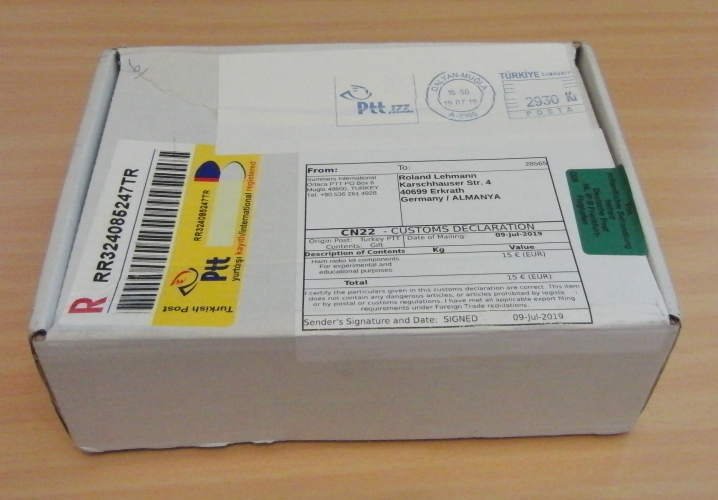
Auf der Suche nach einem neuen Selbstbau-Projekt stieß ich im Internet auf die Seiten der Firma QRP-Labs [http://www.qrp-labs.com/qcx.html], die u.a. zum Preis von 49 USD plus 7 USD Versandkosten einen Single-Band QRP-Transceiver, den QCX, als Bausatz anbietet (QRP CW XVR). Er ist verfügbar für die Bänder 80, 60, 40, 30, 20 und 17m. Ich bestellte die Version für das 40m – Band, und nach etwa 2 Wochen lieferte der Postbote ein handliches kleines Päckchen, das den Bausatz enthielt:

Life is too short for QRP??

Radio amateurs (those who have a class A license) in Germany may operate with a maximum transmit power of 750 Watts. The majority of the amateur radio transceivers on the market have a transmit power of 100 Watts, which in most cases is sufficient to be heard all over the world, depending of course on the actual propagation conditions. If you use your transmitter to drive a power amplifier with 750 Watts, the HF signal will improve by 1 or 2 S-units at the receiver side. This is not very much, but may be good enough in limited conditions, to make a radio contact better or even just possible. It may also be better in a pile-up, where your signal level is overhead the crowd of the other calling stations.

So far, so good. But why should I voluntarily operate with a low transmit power of no more than 5 Watts?

5 Watts are one twentieth of 100 Watts, or, as a technician would say: 13 dB less. 13 dB corresponds to about two S-units. This means, a radio signal coming in with a strength of S9 would  still be well received with S7, if the transmit power had been reduced from 100 to 5 Watts. At the same time, the transmitter would save roughly about 95% of electrical energy.

This saving of energy is a main aspect for the use of QRP radios, especially in those cases, where transceivers are powered by batteries or solar panels and operated on a mountain summit or elsewhere outdoor in nature and open air.

But operating QRP has its attraction at the home station as well, for example for just finding out, how far in the world you can be heard with only 5 Watts. My personal record in QRP radio contact was with Allen, HC2A, located in Guayaquil, Ecuador, over a distance of 6,200 miles (9,977 km) on the 15 m band in Morse telegraphy mode, dated October 23, 2010 at 17:45 UTC. Allen worked with 100 Watts and a 3-element Yagi and I worked with the Flex-1500, running about 5 Watts into a Long Wire antenna. This is some impressing 1,240 miles (2000 kilometres) per Watt!

Enough for the preface. The Flex-1500 is history and found a new owner some years ago. I had turned my interests to DX hunting and was active on the shortwave bands with 100 Watts in the last years.

In search for a new homebrew project, I encounterd the Internet site of a company named QRP-Labs [http://www.qrp-labs.com/qcx.html], which, amomg others, offers a single band QRP transceiver kit, the QCX (QRP Labs CW XVR). It is available for the Amateur bands 80, 60, 40, 30, 20, and 17m.

I ordered the 40m version, and after about two weeks the postman delivered a handy small parcel which contained the QCX kit:

QCX_Box

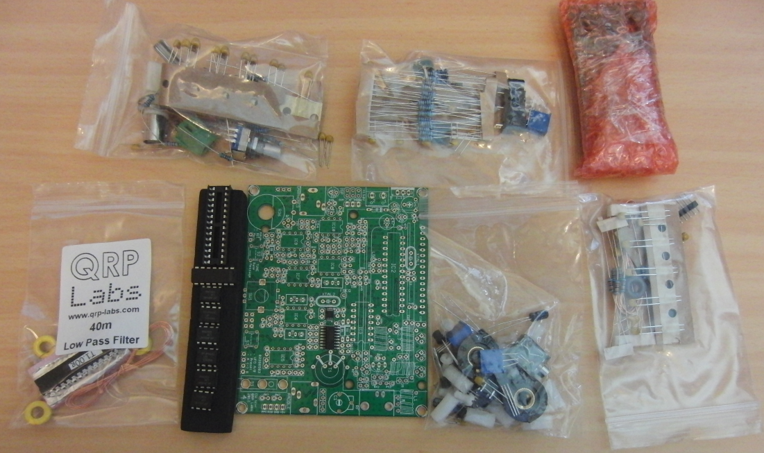
Der Inhalt bestand aus einer Handvoll kleiner Plastiktüten mit vielen Bauteilen, einem Streifen Schaumstoff, auf den diverse ICs gesteckt waren, einer kleinen Platine mit dem LCD-Modul sowie der Hauptplatine, die bereits mit zwei SMD-Chips bestückt war. Alle sonstigen Bauelemente sind bedrahtet.

Als erstes war eine Inventur anhand der Stückliste angesagt. Die Stückliste, sowie die Bauanleitung, eine ausführliche und auch verständliche Schaltungsbeschreibung, sowie die Bedienungsanleitung sind in einem 143-seitigen PDF- Dokument zusammengefasst, das man sich bei QRP-Labs herunterladen kann. Die neueste Version 4.0 liegt nur in englischer Sprache vor, ältere Versionen, z.B. 3.0, sind u.a. auch in Deutsch verfügbar (Stand Oktober 2019).

Inside the parcel was a handful of small plastic bags with lots of components, a strip of foamed plastic, which held numerous ICs, a small PCB with the LCD module as well as the main PCB, that was equipped with two SMD chips already. All other components are conventional wire-through.

The first step was an inventory based on the bill of materials. This bill of meterials, as well as the construction guide, a detailed and easily understandable circuit description and the operating instructions are comprised in a 143 page PDF document, which you can download from the QRP-Labs website. As of October 2019, the latest version 4.0 is available in English language only. Older versions, e.g. 3.0 are available in German and numerous other languages.

QCX_Box_Contents

Alle Bauelemente waren vollständig vorhanden, und somit konnte es ans Bestücken der Platine gehen. Anhand der Bauanleitung geht man dabei Schritt für Schritt vor, hakt jeden Schritt ab und kann sich so sicher fühlen, dass man nichts vergessen hat. Gutes Licht, eine Lupe bzw. Lupenbrille und ein guter Lötkolben mit feiner Spitze, sowie exaktes Identifizieren des einzulötenden Bauteils und genaues Nachkontrollieren sämtlicher Lötstellen sind dabei die Voraussetzungen für gutes Gelingen.

Insgesamt sind 65 Widerstände (stehende Montage), 53 Kondensatoren, 7 Transistoren, 5 Dioden, 9 ICs, 2 Quarze, drei Trimmpotis, ein Trimmkondensator, das Lautstärke-Poti, der Encoder und ein paar elektromechanische Bauelemente (Buchsen, Drucktaster etc.) zu bestücken. Außerdem sind auf 5 Ringkernen (Toroiden) 4 Spulen und ein Transformator (T1) mit einer Primärwicklung mit Anzapfung und zwei Sekundär- wicklungen anzufertigen. Letzterer ist ziemlich knifflig, was das Wickeln und das anschließende Einlöten in die Platine betrifft. Einer der letzten Bestückungsschritte ist das Einlöten von Stift- und Buchsenleisten. Diese verbinden die LCD-Sub- Platine mit der Hauptplatine.

The components check passed OK, and so the next step was populating the printed cicuit board. In accordance with the construction guide you go step by step, put a checkmark at each step description and feel certain that you did not omit anything. A good working lamp, magnifying glass and a proper fine-tipped soldering iron, as well as an exact identificaton of the components to be instelled and an accurate inspection of all solder joints are the prerequisits for a succesful completion of the project.

In summary there are 65 resistors (upright installation), 53 capacitors, 7 transistors, 5 diodes, 9 ICs, 2 crystals, 3 trim potentiometers, one trim capacitor, the volume potentiometer, the rotary encoder and some electro-mechanical components (sockets, push buttons etc.) to be installed. In addition, you have to wind and install 4 inductors and one transformer on 5 toroids. Winding and then installing transformer T1, which has a tapped primary and two secondary windings, is a bit tricky and requires good fine motoric skills. One of the last steps is the installation of a couple of multi-pole in-line pin and socket connectors. These are used to connect the LCD submodule with the main cicuit board.

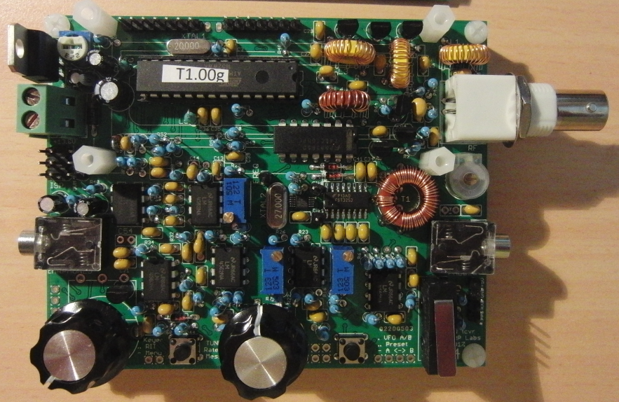
QCX_finished

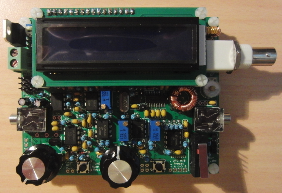
Oben ist die Platine nach Fertigstellung abgebildet. Unten nach Aufstecken des LCD-Moduls. Der geschätzte Zeit - aufwand bis hierher betrug etwa 8 bis 10 Stunden. Ich habe nicht auf die Uhr gesehen und die Bauabschnitte auf mehrere Tage verteilt.

The picture above shows the circuit board after completion. The picture below after installing the LCD submodule. The estimated time effort until now was approximately 8 to 10 hours. I didn’t look at the clock and spread the constructon steps over several days.

QCX_finished_w_LCD

Somit war der magische Moment gekommen: erstmals sollte die Betriebsspannung angelegt werden. Würde irgendwo Rauch aufsteigen? Würde das Display einfach dunkel bleiben? Leider war ja im Laufe des gesamten Zusammenbaus kein Zwischentest eines bestimmten Schaltungsteils erfolgt. Es war alles komplett bestückt und es durfte kein einziger Fehler unterlaufen sein.

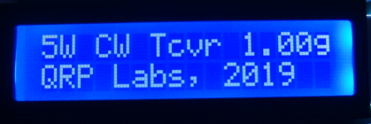
Nein, nachdem das 13,8 VDC Netzteil eingeschaltet war, entstand kein Rauch, und  (Uff!) das Display zeigte die Start - meldung des Mikroprozessors an:

So the magical moment had come: the QCX transceiver had to be powered up for the first time. Would smoke be coming out somewhere? Would the LCD simply display nothing? During the complete assembly of the kit there had been no interim test of any circuit stage. All the components had been installed completely and there should have been no mistake whatsoever.

No, after switching on the 13,8 VDC power supply no smoke emerged anywhere, and (relief!) the LCD displayed the start message of the microprocessor:

LCD_message

Der Abgleich war relativ einfach und bestand aus dem Einstellen eines Trimmkondensators und dreier Spindel- Potenziometer anhand einer detaillierten Beschreibung im Handbuch. Man benötigt keine Messgeräte dafür, denn alle erforderlichen Messmittel sind im QCX bereits eingebaut, wie ein Signal-Generator, ein digitales Voltmeter, ein Frequenz- zähler und ein HF-Leistungsmessgerät.

Ein erster Test unter Zuhilfenahme meines Stations- transceivers vermittelte Zuversicht, dass der QCX tatsächlich funktionierte. An der BNC - Antennenbuchse des QCX wurde eine 50-Ohm-Dummyload aufgesteckt, der Stations-TRX auf 1 Watt heruntergeregelt (weniger geht nicht), und sein Signal war mit dem QCX laut und deutlich zu lesen. Umgekehrt war auch das Sendesignal des QCX im Stations-TRX genau an der erwarteten Frequenz mit ordentlichem S-Meterausschlag zu hören, obwohl der QCX nur in die Dummyload sendete.

Erste Betriebserfahrungen sollte der QCX beim Scandinavian Activity Contest CW am Wochenende 21. Und 22. September bringen. Hier konnte ich innerhalb von 2 Stunden ohne große Anstrengungen 25 QSOs mit Stationen aus OH, OZ, SM und LA loggen. Mit den paar Watt kommt man natürlich nicht immer direkt zum Zug, wenn auch andere QRO-Stationen anrufen, aber mit ein wenig Geduld und nach 1 bis 5 Anrufen wurde ich meistens gehört und bekam einen Report.

The alignment procedure was relatively simple and consisted of adjusting one trim capacitor and three muti-turn spindle potentiometers following the detailled description in the assembly manual. You don’t need a professional gallery of measuring instruments, as all required measuring devices are built-in in the QCX: a signal generator, digital volt meter, frequency counter and RF power meter.

A first test with support of my main station transceiver provided confidence that the QCX was indeed functioning alright. A 50 Ohm dummy load was plugged onto the BNC antenna connector, the station transceiver output power adjusted down to 1 Watt (no lower power possible), and its signal was readable with the QCX loud and clear. The other way, also the signal of the QCX could be heard on the station transceiver exactly at the anticipated frequency with a reasonable S-meter reading, although the QCX was transmitting into the dummy load only.

First experiences on the air with the QCX were to be gained during the Scandinavian Activity Contest on the weekend Sept. 21 and 22, 2019. I easily could log 25 stations from OH, OZ, SM and LA within a time period of two hours. With this low power, you will of course not always be heard at first go while other QRO stations are calling at the same time, but with a little patience and after 1 to 5 repeated calls, I was heard and received a contest report.

QCX_operate

Positiv war die Empfindlichkeit des Empfängers. Die weitest entfernten Stationen, die ich in dem Contest hören konnte, waren einige aus den USA und Brasilien und JT5DX (Mongolei), immerhin.

Negativ fiel zuerst auf, dass der QCX offensichtlich keine AGC besitzt, also keine automatische Regelung der HF- bzw. NF-Verstärkung. Hatte ich vorher auf eine Station mit schwachem Signal abgestimmt und das Lautstärke-Poti etwas weiter aufgedreht, waren nach dem Weiterdrehen des VFO auf ein starkes Signal die akustischen Rezeptoren meiner Ohren in akuter Lebensgefahr. Da muss man immer eine Hand am Lautstärkeregler haben.

Zweitens zeigte sich das 200 Hz CW-Filter zwar als klingelfrei aber nicht besonders steilflankig. Nun ja, das ist kein Quarzfilter sondern 'nur' ein auf RC-Schaltkreisen basierendes Filter im NF-Bereich, da bin ich wohl von meinem Stations-TRX (Elecraft K3S) mit DSP und Quarz bestückten Roofing-Filtern Besseres gewohnt. Jedenfalls waren in dem durch den Contest stark belebten 40m Band auch Signale zu hören, die gut 500 Hertz oder mehr neben der eingestellten Frequenz lagen. Da muss die Filterung eben durch das Gehör erfolgen.

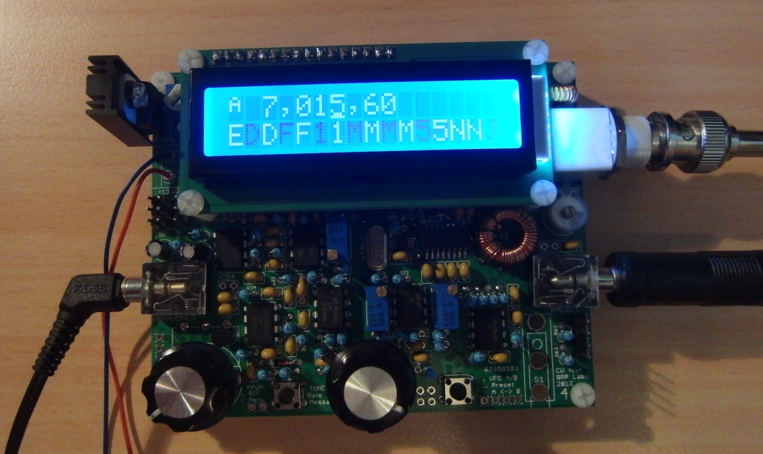
Der CW-Decoder funktioniert so, dass man in der unteren Zeile des Displays den decodierten Text als Laufschrift lesen kann. Er ist im Vergleich nicht schlechter und nicht besser, als alle CW-Decoder, die ich bisher kenne. Ist die Gebeweise der empfangenen Station schlecht oder sind QRM / QRN / QSB im Spiel, ist die Decoderleistung entsprechend eingeschränkt. Der beste CW-Decoder ist halt immer noch das Gehirn des geübten Telegrafisten.

Ansonsten hat der QCX dank Ausnutzung des großen Speichers im ATMega-Prozessor eine enorme Menge an Einstellmöglichkeiten in seiner umfangreichen Menü-Struktur, die sich durchaus mit den großen und teuren Transceivern messen kann. Allerdings hat er nur 4 Bedienungselemente, nämlich das Lautstärke-Poti, zwei Taster (Select und Exit) und einen VFO-Knopf (Impulsgeber mit zusätzlicher Drucktaster-Funktion). Die Menü-Funktionen umfassen dagegen 9 Hauptebenen mit jeweils bis zu 13 Unterebenen. Gut, dass es da eine Bedienungsübersicht (Operation Reference, oder auch Spickzettel / Cheat Sheet) im Handbuch gibt. Diese eine DIN A4 Seite sollte man sich unbedingt ausdrucken und zumindest in der Einübungsphase immer zur Hand haben.

Zur Technik des Transceivers: Dahinter steht die brillante Entwicklung von Hans Summers, GØUPL. Ursprünglich war der Bausatz für das RSGB Youngsters On The Air (YOTA) Sommer - Camp im August 2017 geplant und sollte Jugendliche für die Amateurfunktechnik und für den Selbstbau begeistern. Die Begeisterung war in der Tat groß, und das Interesse der Amateurfunk-Gemeinde ging weit über diese Veranstaltung hinaus, so dass inzwischen über 7000 (!) Bausätze weltweit verkauft wurden. Man sehe sich nur die technischen Merkmale an:

  • Alle Bauteile auf einer Platine
  • Professionelle doppelt kaschierte Platine, 10 x 8 cm, mit Bestückungsdruck
  • Ausgangsleistung 3 .. 5 Watt, abhängig von der Versorgungsspannung (7 – 16 V)
  • Klasse E Sendeendstufe, hoher Wirkungsgrad ohne Kühlkörper
  • Effizientes Tiefpass-Filter zur gesetzkonformen Unterdrückung unerwünschter Oberwellen
  • CW Impulsformung zur Unterdrückung von Tastklicks
  • Hervorragende Empfangseigenschaften mit mind. 50 dB Seitenband-Unterdrückung
  • 200 Hz CW Filter, klingelfrei
  • Direkt - digitaler Synthesizer basierend auf dem modernen Si5351A Chip
  • VFO Einstellung mittels Dreh-Impulsgeber
  • LCD Display mit 2 Zeilen à 16 Zeichen
  • Eingebaute Tast-Elektronik für Paddle – Taste, aber auch Betrieb mit Handtaste wählbar
  • DSP basierender CW-Decoder mit Echtzeit-Anzeige
  • Signalgenerator, Multimeter, Frequenzzähler eingebaut zur Abgleich-Unterstützung

Das Design des Empfängers, kurz beschrieben, basiert auf Direktüberlagerung mit Demodulation durch einen Quadratur- Abtast-Detektor (Quadrature Sampling Detector, kurz QSD, auch bekannt als Tayloe Detector oder "IQ-Mixer"). Diese Technik wurde auch schon u. a. in den frühen Versionen der Flex Radio SDR – Transceiver angewandt und verspricht eine gute Großsignalfestigkeit und niedrige Verluste. Der QSD liefert zwei genau um 90 Grad versetzte Niederfrequenz- signale (I & Q), die ein Phasenschieber- Netzwerk ansteuern, bestehend aus je zwei 1-zu-4 Multiplexern und OP- Amps, wodurch das unerwünschte Seitenband-Signal unterdrückt wird. Danach folgen ein NF – CW – Filter mit 200 Hz Bandbreite und ein Audio-Verstärker für Kopfhörerbetrieb.

Der VFO wird mit dem Si5351A Chip mit externer Quarz- referenz realisiert. Dieser Chip enthält insgesamt 3 digitale PLL-Schaltkreise und wird von einem ATMega328P Mikroprozessor gesteuert.

Für den Sendezweig wird das CLK2-Signal des Si5351A zunächst durch zwei aufeinanderfolgende NAND-Gatter auf einen Pegel von 5 Vpp angehoben. Damit werden drei parallel geschaltete N-Kanal-MOSFETs vom Typ BS170 angesteuert. Diese "Sendeendstufe" aus billigen Kleinsignal-Transistoren arbeitet in Klasse E - Betrieb und wird quasi mit Rechteck-Signalen betrieben. Der Wirkungsgrad dieser Stufe liegt bei etwa 90%, wobei kaum Abwärme, aber eine Menge Oberwellen entstehen. Ein Kühlkörper kann somit entfallen, und zwangsläufig folgt ein wirksamer 7-Element – Tiefpass. An der BNC-Antennenbuchse stehen dann, je nach Höhe der Betriebsspannung, etwa 3 bis 5 Watt Sendeleistung zur Verfügung.

Zusammenfassend lässt sich sagen, dass man für die rund 50 Euro einen sehr guten QRP-Transceiver bekommt, der mit einigen wenigen Einschränkungen prima funktioniert. Beim Zusammenbau erfordert  er Sorgfalt, die aber mit guter Empfangsleistung und Spaß beim Betrieb belohnt wird.

Bei QRP Labs wird seit einiger Zeit auch ein Nachfolger angekündigt, der QSX  Transceiver, ein 10 Watt Allband-Transceiver, der auch SSB, RTTY, PSK etc. kann. Der Bausatzpreis soll in der Größenordnung von 150 US Dollar liegen. Es bleibt spannend zu sehen, was sich da tut.

A positive perception was the sensitivity of the receiver. Stations most distance I could hear during the contest were a couple of US and Brazilian callsigns and JT5DX from Mongolia. Not so bad!

The first negative impression was, the QCX obviously does not have an AGC, an automatic control of the HF or AF gain. If I had previously tuned to a station with weak signal and had turned up the volume potentiometer a little bit, and then moved the VFO frequency to a strong signal, the acoustic receptors of my ears got into acute mortal danger. The QCX seems to require one hand at the volume potentiometer at all times while you are moving through the band.

Second, the 200 Hz CW bandpass filter turned out to be free of ringing, but not particularly narrow. Well OK, this is not a high-tech crystal filter but just an RC circuit based filter in the AF stage. I admit, I’m  used to know better filtering in my main station Transceiver (Elecraft K3S) with DSP and multi-crystal roofing filters. Anyway, in the 40 m band crowded by lots of contest stations I could also hear signals which were more than 500 Hertz away from the current VFO frequency. So the better  filtering of CW signals has often to be carried out by the operator ears.

The CW decoder works in a way that you can read the decoded text as a ‘ticker’ in the lower row of the LCD display. The decoder quality is no better and no worse than all CW decoders that I know so far. If the morse coding of the received station is bad, or if QRM / QRN / QSB are deteriorating the receive quality, the decoder performance is quite limited. After all, the best CW decoder is the brain of the well-trained CW operator.

In other respects, the QCX transceiver, due to the utilization of the large storage space of the ATMega processor, has an enormous quantity of adjustment items in its extensive menu structure. This menu structire definitely can be compared to the big and expensive amateur radio transceivers. Nevertheless it only has four control elements, specifically the volume pot, two pushbuttons (Select and Exit) and a VFO knob (rotary encoder with an additional pushbutton function). The menu functions, in contrast, consist of 9 main levels, each with up to 13 sub-levels. So it is good to know there is an Operation Reference (aka ‘Cheat Sheet’) in the operator’s manual. This is one DIN A4 formatted page, which I recommend you should print out and always keep at hand, at least while you are in the training phase.

Now to th technical details of the QCX: The genius of this brilliant product is Hans Summers, GØUPL. Originally this kit was planned for the RSGB Youngsters On The Air (YOTA) summer camp event in August 2017, and it should evoke the interest of young persons in Amateur Radio and electronic DIY projects. The interest of the Amateur Radio community was indeed tremendous, and it expanded substantially beyond this YOTA event, in a way that, in the meantime, more than 7000 (!) kits of the QCX have been sold worldwide.  Just take a look at the technical features:

  • All components on a single PCB
  • Professional double sided circuit board, 10 x 8 cm, with component silkscreen
  • Output power 3 .. 5 Watt, depending on supply power voltage (7 – 16 V)
  • Class E final power amplifier, with high efficiency and without heat sink
  • An efficient low-pass filter to achieve suppression of harmonics as required by the legal commandments.
  • CW pulse shaping to suppress key-clicks
  • Outstanding receiver performance with more than 50 dB sideband suppresson
  • 200 Hz CW Filter, with no ringing
  • Direct digital synthesizer based on the state-of-the-art Si5351A chip
  • VFO tuning by means of a rotary encoder
  • LCD display with 2 lines of 16 characters
  • Built-in keying circuit for iambic paddle and optional operation with standard manual key
  • DSP based CW decoder with real-time display
  • Signal generator, multimeter, frequency counter built-in to support the alighnment process
     

The receiver design, in summary, is based on direct conversion by means of a Quadrature Sampling Detector, (QSD), also known as Tayloe Detector or "IQ-Mixer". This design was, among others, applied in the early versions  of the Flex Radio SDR transceivers. It is known for good selectivity and low signal losses.  The QSD provides two AF signals (I & Q), which are shifted by exactly 90 degrees.  These are fed into a phase shifting network, each one consisting of two 1:4 high-speed multiplexers and OPAmps, which suppress the unwanted sideband. In the following AF  stage  an audio filter with a bandwidth of  200 Hz and an audio amplifier drive the headphone output.

The VFO is built around the Si5351A chip with  an external crystal controlled refence oscillator. This chip contains no less than three digital PLL circuits which are controlled by an  ATMega328P microprocessor.

In the transmit circuit, the CLK2 signal of the Si5351A chip is first amplified to a level of 5 Vpp by two sequenced NAND gates. These feed three N-channel MOSFET transistors in parallel circuit. This final transmit power amplifier stage,  consisting of cheap low-level transistors, is designed for class-E operation and operates in switching mode with square wave signals. The efficiency of this amplifier stage is near 90 percent. This design produces very low heat dissipation but is also capable to produce a lot of harmonic waves. In consequence, we don’t need a heat sink, but some effective harmonics suppression is absolutely necessary. This is done by a 7-element low-pass filter. So the BNC antenna socket supplies about 3 to 5 Watts of transmit power, depending on  the supply voltage.

In conclusion I can say, for about 50 Euros you are getting a very good QRP-Transceiver, which,  besides  a few restraints, does an excellent job. The assembly requires some practice and good workmanship, which after all are rewarded with good receiver performance and a lot of fun on the air. 

Not long ago, QRP Labs announced a new development, the QSX transceiver, which is said to be a 10 Watt all-band transceiver, featuring not only CW mode but also SSB, RTTY, PSK etc. The transceiver kit would be in the range of about  150 US Dollars. I sure will keep an eye on this.

Home   Station   PA_DL1EAL   Morse Telegraphy   QRP   Impressum